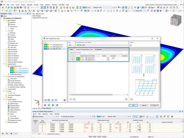
In the "Group of Imperfection Cases" imperfection case, you can enter several geometric imperfection cases. This allows you to carry out GMNIA analyses where several geometric imperfections have to be superimposed.
Go to Explanatory Video
Use RWIND 2 Pro to easily apply a permeability to a surface. All you need is the definition of
- the Darcy coefficient D,
- the inertial coefficient I, and
- the length of the porous medium in the direction of flow L,
to define a pressure boundary condition between the front and back of a porous zone. Due to this setting, you obtain the flow through this zone with a two-part result display on both sides of the zone area.
But that's not all. Furthermore, the generation of a simplified model recognizes permeable zones and takes into account the corresponding openings in the model coating. Can you waive an elaborate geometric modeling of the porous element? Understandable – we have good news for you then! With a pure definition of the permeability parameters, you can avoid complex geometric modeling of the porous element. Use this feature to simulate permeable scaffolding, dust curtains, mesh structures, and so on.
More Information
RFEM allows you to use a special line hinge to model the special properties of the connection between the reinforced concrete slab and masonry wall. This limits the transferable forces of the connection depending on the specified geometry. You guess right: This means that the material cannot be overloaded.
The program develops interaction diagrams that are applied automatically. They represent the various geometric situations and you can use them to determine the correct stiffness.
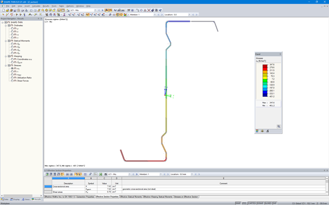
SHAPE‑THIN determines the effective cross-sections according to EN 1993‑1‑3 and EN 1993‑1‑5 for cold-formed sections. You can optionally check the geometric conditions for the applicability of the standard specified in EN 1993‑1‑3, Section 5.2.
The effects of local plate buckling are considered according to the method of reduced widths, and the possible buckling of stiffeners (instability) is considered for stiffened sections according to EN 1993‑1‑3, Section 5.5.
As an option, you can perform an iterative calculation to optimize the effective cross-section.
You can display the effective cross-sections graphically.
Read more about designing cold-formed sections with SHAPE-THIN and RF-/STEEL Cold-Formed Sections in the technical article "Design of Thin-Walled, Cold-Formed C-Section According to EN 1993‑1‑3".
Design of Thin-Walled, Cold-Formed C-Section According to EN 1993-1-3 More about RF-/STEEL Cold-Formed Sections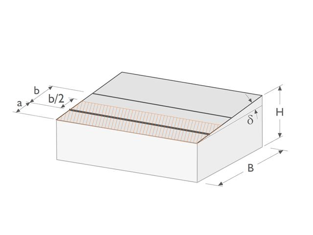
- Design of the following geometrical types:
- Single-span beams with and without cantilevers
- Continuous beams with and without cantilevers
- Hinged girder system (Gerber beams) with and without cantilevers
- Automatic generation of wind and snow loads
- Automatic creation of required combinations for the ultimate and serviceability limit states, as well as fire resistance design
- For design according to EC 5 (EN 1995), the following National Annexes are available:
-
 DIN EN 1995-1-1/NA:2013-08 (Germany)
 -
 NBN EN 1995-1-1/ANB:2012-07 (Belgium)
 -
 DK EN 1995-1-1/NA:2011-12 (Denmark)
 -
 SFS EN 1995-1-1/NA:2007-11 (Finland)
 -
 NF EN 1995-1-1/NA:2010-05 (France)
 -
 UNI EN 1995-1-1/NA:2010-09 (Italy)
 -
 NEN EN 1995-1-1/NB:2007-11 (Netherlands)
 -
 ÖNORM B 1995-1-1:2015-06 (Austria)
 -
 PN EN 1995-1-1/NA:2010-09 (Poland)
 -
 SS EN 1995-1-1 (Sweden)
 -
 STN EN 1995-1-1/NA:2008-12 (Slovakia)
 -
 SIST EN 1995-1-1/A101:2006-03 (Slovenia)
 -
 CSN EN 1995-1-1:2007-09 (Czech Republic)
 -
 BS EN 1995-1-1/NA:2009-10 (the United Kingdom)
-
- Consideration of optimization options by user specifications according to the respective standard:
- Shear force reduction of single loads near support
- Shear force reduction of load introduction at the cross-section top point
- Moment redistribution in support zone
- Reduction of torsional stress by means of user-defined entry of moment
- Increase of bending stiffnesses for flat-ended or edgewise bending strains
- Simple geometry input with illustrative graphics
- Extensive material library for both standards
- Optional extension of material library by further materials
- Extensive library of permanent loads
- Allocation of framework to service classes and specification of service class categories
- Determination of design ratios, support forces, and deformations
- Info icon indicating successful or failed design
- Color reference scales in result tables
- Direct data export to MS Excel
- Program languages: English, German, Czech, Italian, Spanish, French, Portuguese, Polish, Chinese, Dutch, and Russian
- Verifiable printout report, including all required designs. Printout report available in many output languages; for example, English, German, French, Italian, Spanish, Russian, Czech, Polish, Portuguese, Chinese, and Dutch.
- Direct import of stp files from various CAD programs
- Design of the following geometrical types:
- Single-span beams with and without cantilevers
- Continuous beams with and without cantilevers
- Hinged girder system (Gerber beams) with and without cantilevers
- For design according to EC 5 (EN 1995), the following National Annexes are available:
-
DIN EN 1995-1-1/NA:2013-08 (Germany)
-
NBN EN 1995-1-1/ANB:2012-07 (Belgium)
-
DK EN 1995-1-1/NA:2011-12 (Denmark)
-
SFS EN 1995-1-1/NA:2007-11 (Finland)
-
NF EN 1995-1-1/NA:2010-05 (France)
-
UNI EN 1995-1-1/NA:2010-09 (Italy)
-
NEN EN 1995-1-1/NB:2007-11 (Netherlands)
-
ÖNORM B 1995-1-1:2015-06 (Austria)
-
PN EN 1995-1-1/NA:2010-09 (Poland)
-
SS EN 1995-1-1 (Sweden)
-
STN EN 1995-1-1/NA:2008-12 (Slovakia)
-
SIST EN 1995-1-1/A101:2006-03 (Slovenia)
-
CSN EN 1995-1-1:2007-09 (Czech Republic)
-
BS EN 1995-1-1/NA:2009-10 (the United Kingdom)
-
- Automatic generation of wind and snow loads
- Multiple optional reductions according to the selected standard
- Simple geometry input with illustrative graphics
- Free entry of tapered geometries. Free selection of the grain angle allows for user-defined design of the compressive and tensile areas for bending
- Comprehensive and extensible material library
- Determination of design ratios, support forces, and deformations
- Color reference scales in result tables
- Direct data export to MS Excel
- DXF interface for preparation production documents in CAD
- Program languages: English, German, Czech, Italian, Spanish, French, Portuguese, Polish, Chinese, Dutch, and Russian
- Verifiable printout report, including all required designs. Printout report available in many output languages; for example, English, German, French, Italian, Spanish, Russian, Czech, Polish, Portuguese, Chinese, and Dutch.
- Direct import of stp files from various CAD programs
.png?mw=640&hash=688fdfc8af4828c08e9851cddb103a1e86cb899a)
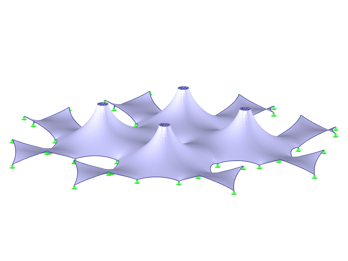
- Form-finding of:
- tension-loaded membrane and cable structures
- compression-loaded shell and beam structures
- mixed tension- and compression-loaded structures
- Consideration of gas chambers between surfaces
- Interaction with supporting structure (substructure design according to various standards)
- Surfaces as a 2D and members as a 1D element
- Definition of different prestress conditions for surfaces (membranes and shells)
- Definition of forces or geometrical requirements for members (cables and beams)
- Consideration of individual loads (self‑weight, inner pressure, and so on) in the form‑finding process
- Temporary support definitions for the form-finding process
- Automatic preliminary form-finding of membrane surfaces (more information...)
- Definition of isotropic or orthotropic material for structural analysis
- Optional definition of free polygon loads
- Transformation of form‑found shape elements into NURBS surface elements
- Possibility of combined form-finding by integration of preliminary form-finding
- Graphical evaluation of the new form using colored coordinates and inclination plots
- Complete documentation of the calculation including user-defined adaptive evaluation figures
- Optional export of the FE mesh as a DXF or Excel file
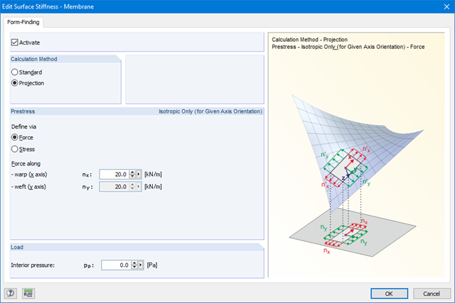
The form-finding function can be activated in the General Data dialog box, Options tab. Prestresses (or geometrical requirements for members) can be defined in the parameters for surfaces and members. The form‑finding process is performed by calculation of an RF‑FORM‑FINDING case.
Steps of the working sequence:
- Creation of a model in RFEM (surfaces, beams, cables, supports, material definition, and so on)
- Setting of required prestress for membranes and force or length/sag for members (for example, cable)
- Optional consideration of other loads for the form-finding process in special form‑finding load cases (self‑weight, pressure, steel node weight, and so on)
- Setting of loads and load combinations for further structural analyses
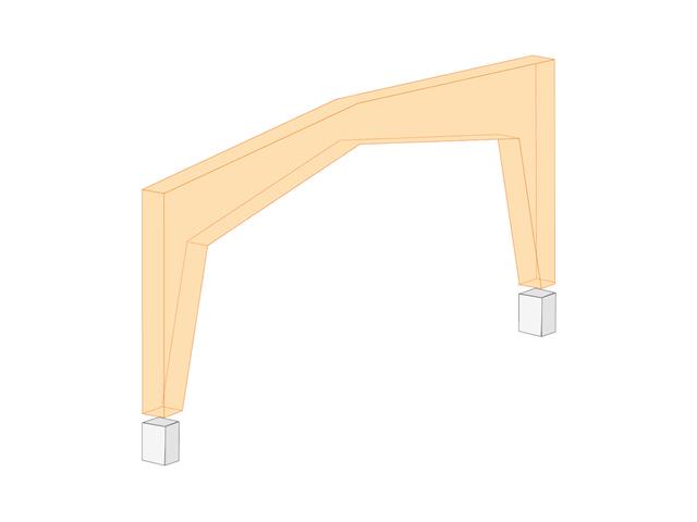
- Design of the following geometrical types:
- Symmetrical / asymmetrical
- Half-frame
- Column sloping inside / outside
- Intermediate piece with / without
- Direction of lamellas can be defined as parallel to inner or outer edge
- For design according to EC 5 (EN 1995), the following National Annexes are available:
-
DIN EN 1995-1-1/NA:2013-08 (Germany)
-
NBN EN 1995-1-1/ANB:2012-07 (Belgium)
-
DK EN 1995-1-1/NA:2011-12 (Denmark)
-
SFS EN 1995-1-1/NA:2007-11 (Finland)
-
NF EN 1995-1-1/NA:2010-05 (France)
-
UNI EN 1995-1-1/NA:2010-09 (Italy)
-
NEN EN 1995-1-1/NB:2007-11 (Netherlands)
-
ÖNORM B 1995-1-1:2015-06 (Austria)
-
PN EN 1995-1-1/NA:2010-09 (Poland)
-
SS EN 1995-1-1 (Sweden)
-
STN EN 1995-1-1/NA:2008-12 (Slovakia)
-
SIST EN 1995-1-1/A101:2006-03 (Slovenia)
-
CSN EN 1995-1-1:2007-09 (Czech Republic)
-
BS EN 1995-1-1/NA:2009-10 (the United Kingdom)
-
- Simple geometry input with illustrative graphics
- Automatic generation of wind and snow loads
- Automatic creation of required combinations for the ultimate and serviceability limit states, as well as fire resistance design
- Possibility to define load cases and load applications
- Extensive material library for both standards
- Optional extension of material library by further materials
- Extensive library of permanent loads
- Allocation of framework to service classes and specification of service class categories
- Determination of design ratios, support forces, and deformations
- Info icon indicating successful or failed design
- Color reference scales in result tables
- Direct data export to MS Excel
- DXF interface for preparation production documents in CAD
- Program languages: English, German, Czech, Italian, Spanish, French, Portuguese, Polish, Chinese, Dutch, and Russian
- Verifiable printout report, including all required designs. Printout report available in many output languages; for example, English, German, French, Italian, Spanish, Russian, Czech, Polish, Portuguese, Chinese, and Dutch.
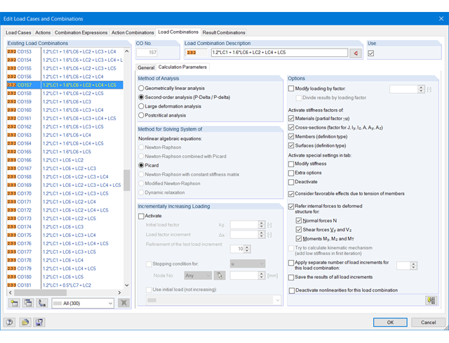
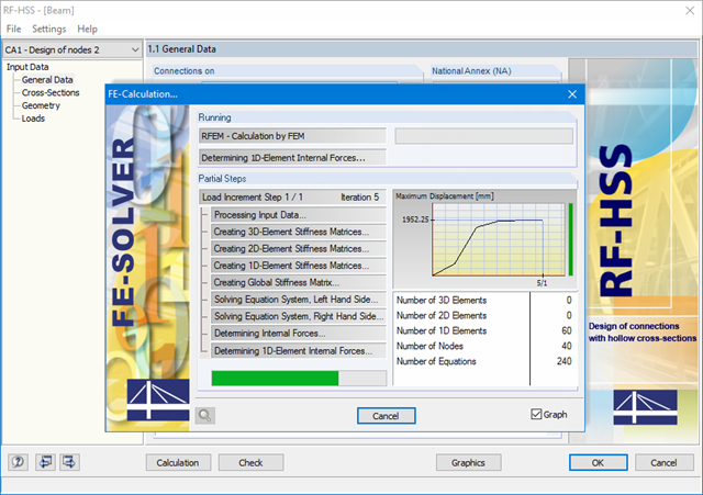
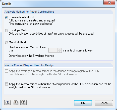
The load cases included in load combinations are added together and then calculated in consideration of the corresponding factors (partial safety and combination factors, coefficients regarding consequence classes, and so on). The load combinations can be created automatically in compliance with the combination expressions of the standard. The calculation can be performed according to the geometrically linear, second-order, or large deformation or as per the post-critical analysis. Optionally, you can define whether the internal forces should be related to the deformed or non-deformed structure.
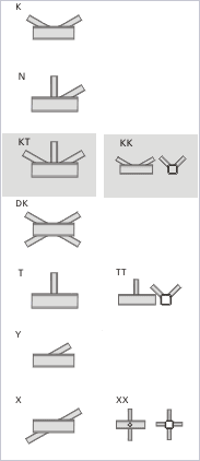
It is possible to select connection nodes graphically in the RFEM/RSTAB model. The relevant cross-section data and geometry are imported automatically. You can also define the parameters of hollow section connections manually. If necessary, you can modify the sections in the module.
The default angle between struts and chords can be modified as well. The geometric relation of the struts to each other is important for the correct choice of design. This relationship can be defined by specifying a gap between the struts or by overlapping them.
A successful design check is based on the plausibility check of the geometric conditions.
The RF-/HSS add-on module performs the calculation for the following designs:
- Flange failure of chord member due to normal force
- Shear failure of chord member due to normal force
- Strut failure due to normal force
- Punching shear due to normal force
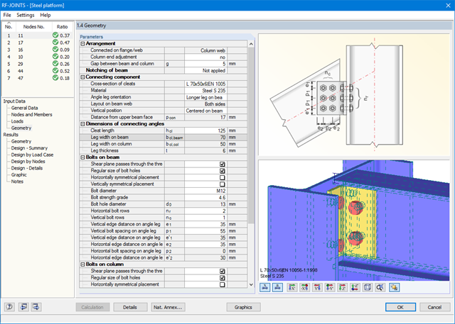
All joint types are considered with the moment release at the column flange, or at the column web in the case of a rotated column. Therefore, the module determines the eccentric moment of a web cleat and fin plate connection, which additionally affects the bolt group at the girder flange.
Further eccentric moments may result from the locations of the angles and sheets. In the case of cleat connection, the forces are transferred separately. Shear forces act on the cleat; tension forces and stabilizing moment are assigned to the bolts. Before the calculation, the connection is checked for geometrical plausibility; for example, the bolt hole spacing and edge distance of the bolts.
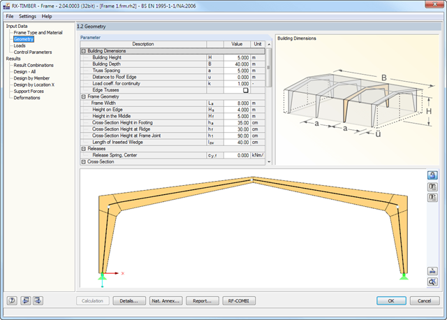
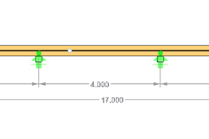
There are various options available for frame modeling. Graphical representations facilitate the geometry input. Modifications are updated automatically. Basic dimensions as well as geometrical data are entered in tables. During the input, the program checks the conditions required for the beam creation (for example, lamellas forming a curve) according to the defined standard. The most important geometry parameters are updated and displayed.
The relevant timber grade of the material can be selected from the material library. All material grades for glulam, hardwood, poplar and softwood timber specified in EN 1995-1-1 are available. Furthermore, it is possible to generate a strength class with user-defined material properties in order to extend the library. Permanent loads (for example, roof structure) can also be entered using the comprehensive and extensible material library.
Generators integrated in RX-TIMBER Purlin allow for convenient generation of various wind and snow load cases. By clicking the information buttons, the map of wind and snow zones for the relevant country is displayed. The corresponding zone can be selected with a double-click. Load cases can be checked graphically. However, you can enter load specifications manually as well. According to the generated loads, the program automatically creates combinations for the ultimate and serviceability limit states as well as for fire resistance design in the background. The generated combinations can be considered or adjusted by user-defined specifications.
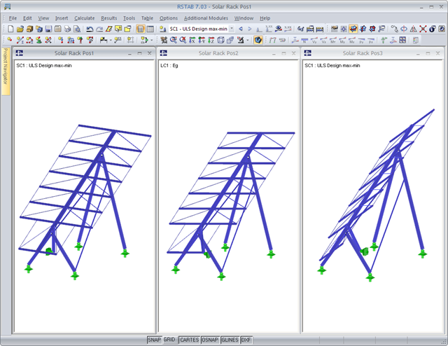
A basic model is created and saved under different names depending on the construction progress. These structural models are then used for the supercombination. The superpositioning can be performed in the same way as for an RSTAB result combination.
By modeling various construction or operational conditions, different geometric boundary conditions can be represented: It is possible to add or remove supports, members, or elastic foundation of the model, for example.
.png?mw=640&hash=9b9d807f48ef10cbb11e804ba19e570f258060db)
- Management of RSTAB models according to construction progress
- Definition of geometric boundary conditions for individual construction and operational conditions
- Access to load cases, load combinations, and result combinations of all structures
- Superposition of the different models in the form of an envelope of all extreme values
- Combination options according to the following standards:
-
 Eurocode
 -
DIN 18800:1990-11
-
DIN 1045:1988-07
-
DIN 1045-1:2008-08
-
DIN 1052:1988-04
-
to DIN 1055-100:2001-03
-
ÖNORM
- Serviceability (unscaled)
-
- Tabular and graphical result display
In order to facilitate the data input, surfaces, members, sets of members, materials, surface thicknesses, and cross-sections are preset in RFEM. It is possible to select the elements graphically using the [Select] function. The program provides access to the global material and section libraries. Load cases, load combinations, and result combinations can be combined in various design cases. You can enter all geometric and standard-specific reinforcement settings for the reinforced concrete design in a segmented window. The geometry entries in both RF‑CONCRETE modules differ from each other.
- In the RF-CONCRETE Members add-on module, for example, This includes, for example, specifications for the curtailment of rebars, number of layers, cutting ability of links, and anchorage type. For the fire resistance design of reinforced concrete members, you have to define the fire resistance class, the fire‑related material properties, and the cross‑section sides exposed to fire.
- In the RF‑CONCRETE Surfaces add‑on module, it is necessary to specify, for example, the concrete cover, the reinforcement direction, the minimum and the maximum reinforcement, the basic reinforcement to be applied, or the designed longitudinal reinforcement, as well as the rebar diameter.
Surfaces or members can be summarized in special "reinforcement groups", each defined by different design parameters. This way, it is possible to efficiently calculate alternative designs with different boundary conditions or modified cross‑sections.